Introduction
-
-
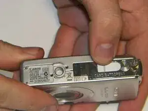
Turn the camera over so that the battery compartment is visible. The compartment should read "Card/Batt. Open".
-
Open the compartment.
-
Lightly push the compartment lid down and outward. The arrow next to "Card/Batt. Open" indicates the direction you should be pushing.
-
-
-
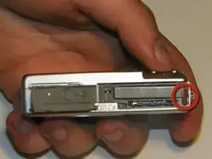
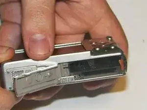
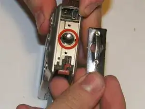
Once the lid is open, the battery and SD card compartments become visible.
-
Notice the red tab on the right side of the battery.
-
Slide this tab off the battery.
-
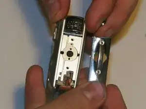
The battery is now free to slide out of the compartment.
-
-
-
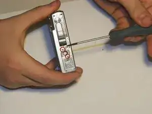
There are six 3mm exterior screws that will need to be removed in order to remove the exterior frame.
-
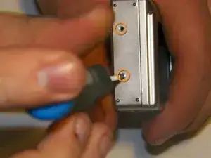
Two screws near the tripod mount on the underside of the camera.
-
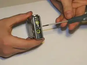
Two screws on the camera left hand side (the face with nothing but screws on it).
-
Two screws on the camera right hand side, by the wrist strap attachment.
-
Remove the screws using the screwdriver.
-
-
-
Remove the wrist strap attachment.
-
Use the spudger to pry it open.
-
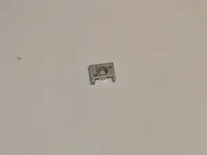
Remove the small circular cover underneath the wrist strap attachment.
-
-
-
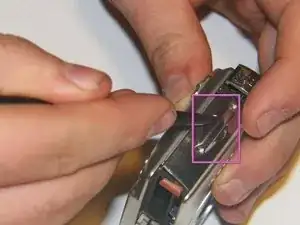
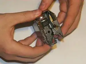
Carefully pull apart the two parts of the exterior frame.
-
Use the spudger to pry apart the two frame components.
-
Once disconnected, the two parts of the frame can be easily separated by using your fingers.
-
The rear frame should be removed first.
-
There should be an O-ring on the front face of the camera. Ensure to keep the O-ring with the front part of the frame.
-
-
-
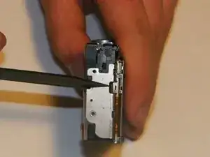
The power and shutter buttons are located on the top of the camera and are removed as a single unit.
-
Use the spudger to lift the power/shutter buttons from the camera.
-
-
-
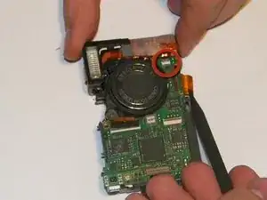
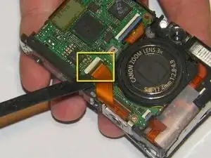
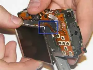
Disconnect the cable that connects the screen to the front motherboard.
-
Using a spudger, unsnap the jawbone connector that holds the cable in
-
Gently pull the cable out using the spudger.
-
-
-
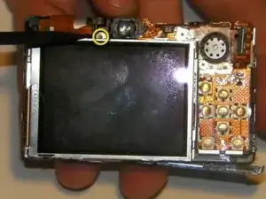
At the back of the camera, there are four 2.5mm screws that will need to be removed in order for the screen to pull off.
-
One at the top of the camera that is connected to a bracket that secures the screen.
-
Two on the back of the camera,near the speaker.
-
One hidden behind the bracket.
-
-
-
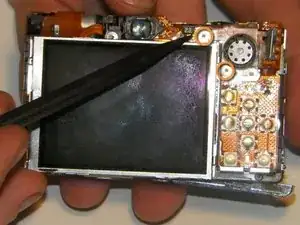
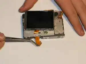
Gently lift the screen and pull it apart from the camera, taking care to unslot the screen brackets from the tabs on the bottom and left side of the camera.
-
Do not pull too hard on the screen as there is still another delicate cable running from the screen to the rear board of the camera.
-
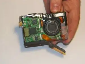
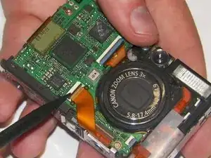
Gently pull the wide ribbon (shown in an earlier step) cable from the front of the camera to the back using tweezers.
-
-
-
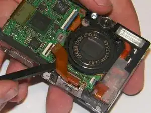
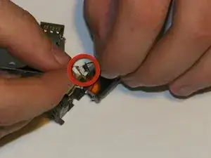
The screen is now connected only by a small cable that runs to the rear board of the camera. Using tweezers, slowly pull the cable out of the connector.
-
For best results, grip the cable as close to the connector as possible.
-
The screen should now be separate from the camera body. Be careful not to harm the connectors on the lens so it will reconnect successfully.
-
-
-
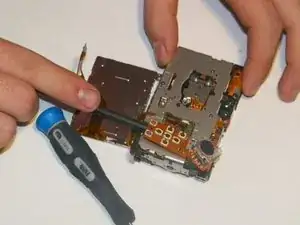
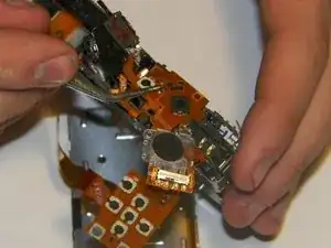
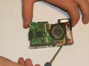
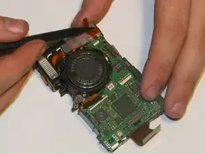
Using the spudger, gently push up the board from the pins underneath it.
-
Follow the board up and around the camera, gently unseating the board and cables.
-
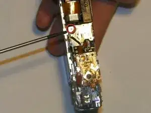
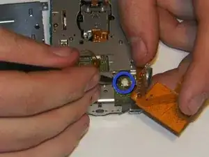
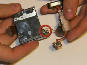
The speaker will still be connected to the board via two small power wires. Use the tweezers to pull and unplug the power connector from the main rear accessory board.
-
-
-
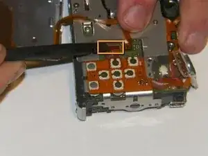
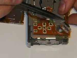
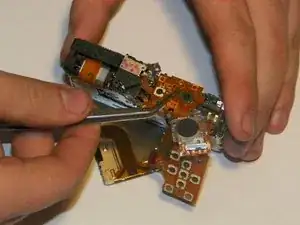
Grip the top control board with the tweezers and gently pull up to unseat it from the placement pins it sits on.
-
If need be, use the spudger to gently pry out the optical viewfinder.
-
-
-
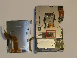
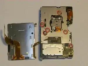
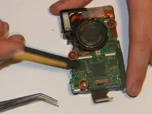
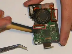
There are six 3mm screws located on the interior frame.
-
Remove the screws with the screwdriver.
-
-
-
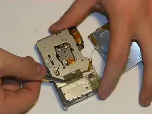
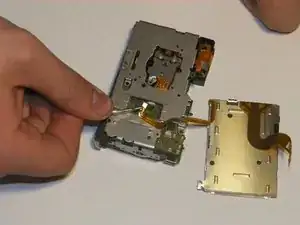
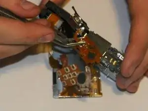
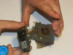
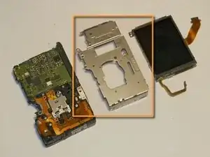
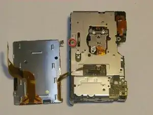
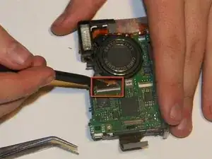
After the screws are removed gently pull the frame away from the rest of the camera.
-
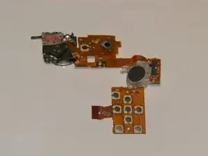
The interior frame should now be disconnected.
-
-
-
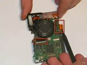
There are two 3.25mm screws that hold the tripod mount in the camera.
-
The first screw is located on the back of the camera above the tripod mount.
-
The second screw is located on the lens side of the camera above the tripod mount.
-
Remove the second screw using the Phillips 00 Screwdriver.
-
-
-
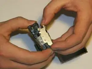
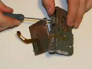
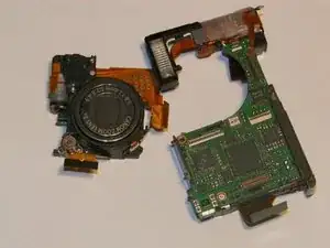
Firmly gripping the front and rear of lens, gently remove the assembly from between the motherboard and the flash assembly.
-
-
-
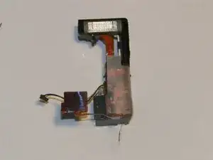
There is a small connector that mounts in the battery compartment that will need to be unplugged for the flash assembly to be fully removed.
-


To reassemble your device, follow these instructions in reverse order.