Introduction
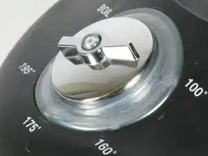
If you have a broken or loose dial, then this guide can help you replace it.
-
-
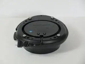
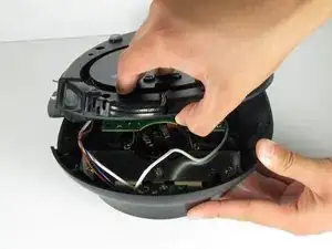
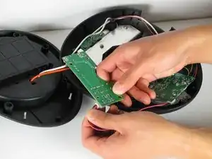
Remove the four 12 mm Phillips #2 screws surrounding the base then lift the bottom half of the base to expose the circuit boards inside the device.
-
-
-
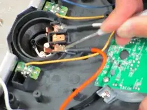
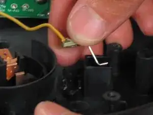
Use the metal spudger to cut open the rubber covering the latch where it clamps onto the copper tab.
-
Unplug wire at heating element by first using the metal spudger to push the latch in and then pushing it out.
-
-
-
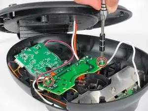
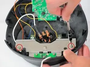
Remove the two 7.5mm Phillips #2 screws from the metal frame.
-
Remove the frame from the assembly.
-
-
-
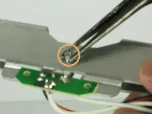
Remove the two 6mm fine thread Phillips #2 screws attaching the small computer chip to the metal frame.
-
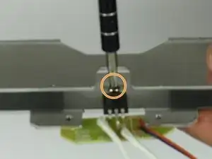
Flip over and remove the 7.5 mm fine thread Phillips #2 screw from the back while holding the 5mm nut on the front securely.
-
-
-
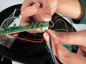
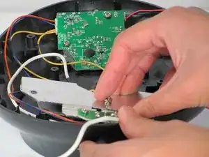
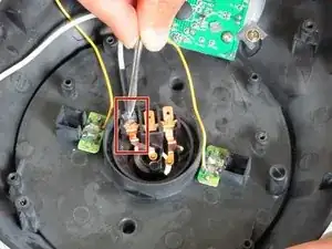
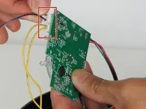
Find the cable that attaches the small computer chip to the heating element connections.
-
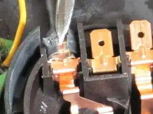
Use the spudger to cut open the rubber coating on the latch where it clamps onto the copper tab.
-
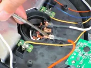
Insert the metal spudger into the rectangular hole on the latch and push toward the tab (away from the wire) to unbend the tab.
-
Push the latch off the tab with the spudger.
-
-
-
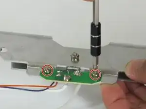
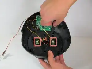
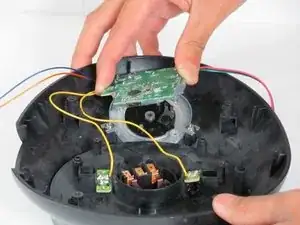
Identify the two computer chips that connect the two yellow wires to the temperature controls.
-
Remove the four 5 mm Phillips #1 screws.
-
Remove the two computer chips from their places.
-
-
-
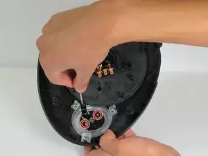
Find the computer chip over the dial.
-
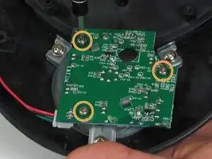
Remove the three 6mm Phillips #2 screws.
-
Remove the computer chip.
-
-
-
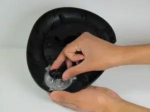
Remove the two 6 mm Phillips #1 screws from the black dial base plate.
-
6 mm Phillips #1 screws
-
Remove the black dial base plate, metal spring, LED tube, and the actual dial.
-
-
-
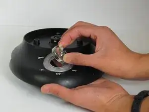
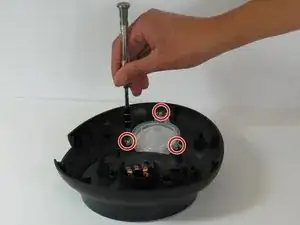
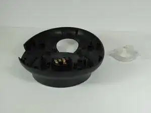
Remove the three 7.5 mm Phillips #2 screws from the dial collar.
-
7.5 mm Phillips #2 screws
-
The dial collar will then come away from the base.
-


To reassemble your device, follow these instructions in reverse order.