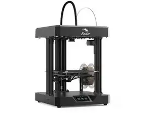
Introduction
Tools
-
-
If the Z-axis is no longer working.
-
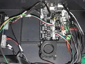
disconnect the power cable to the printer and open the bottom and on the mother board switch the cable to Z-step motor with the one to the extruder step-motor.
-
close the bottom and start the printer in setting mode.
-
request the extruder to move forward a little, and if the Z-motor move, you can confirm the Z-motor is working as expected.
-
You can order a new driver online.
-
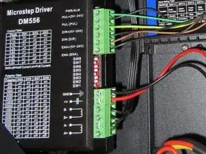
I choose a DM556, because it is cheaper than the DM542.
-
-
-
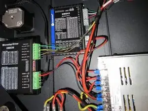
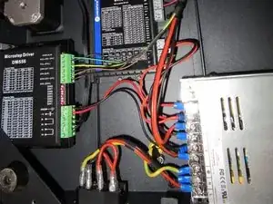
Disconnect the power cable again and open the bottom of the printer
-
There is enough space to place the driver as on the picture.
-
You need to drill two hole in the frame on the back for the two screws to hold the driver.
-
Take you time to mark where you need to drill as it will be visible from the outside later.
-
-
-
Connect the power directly to the 12V power supply.
-
Cut the cable to the Z-axis at approx 15cm from the plug of the motherboard.
-
Save the 15cm left!
-
Connect the A-, A+, B- and B+ to the right place.
-
Use as much as possible the X and Y connection as a reference to connect the Z!
-
-
-
Use new wires to connect the control signals from the mother board to the external driver.
-
Carry over the way is is connected on X and Y.
-
use later zip-tie to prevent all the cable you add to move and vibrate when the printer will be running.
-
-
-
The whole idea is to bypass the original onboard driver (which is under dimension, I think).
-
You can remove the mounting screws of the motherboard to remove the connector and reuse it on the similar position as X and Y.
-
OR you can simply solder the each wire, one by one.
-
-
-
I selected 2,1A: SW1=off SW2=on SW3=on.
-
I selected 3200pulses/rotation: SW5=on SW6=on SW7=off SW8=on to match the the movement of the printing surface.
-
You can close the bottom of the frame and connect back the power cable to give a try!
-


One comment
I’m having an issue with my X-Y motors one of the stepper boards gave out and I bought two of these as a replacement where would I start