Introduction
A printed circuit board (PCB) mechanically supports and electronically connects electronic components using conductive tracks made of copper laminated onto a non-conductive plastic. The PCB reduces the amount of wires in a device and inherently makes any device more reliable. The step by step instructions will describe how to troubleshoot your PCB.
-
-
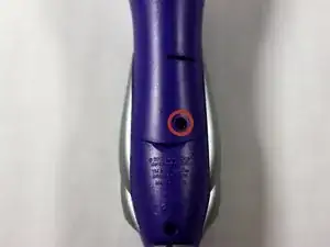
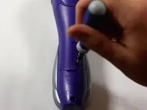
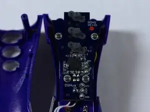
Remove the back panel of the device by unscrewing the single #8 11.6 mm Flathead screw on the back of the device.
-
-
-
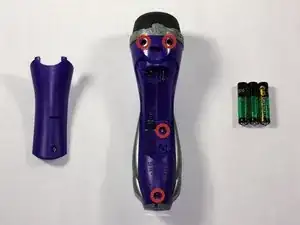
Unscrew the other 4, #8 11.6 mm Phillips Head screws to remove the entire back half of the device.
-
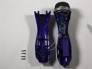
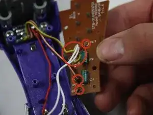
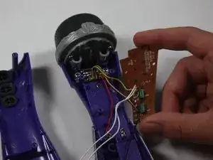
Pull apart the device once screws are loose, splitting the device in half.
-
-
-
Keeping all wires connected to their attachments, place the front half of the device face down.
-
-
-
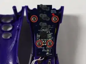
Remove the 2, #8 11.7 mm Phillips Head screws as well as the 2, #8 7.5 mm screws on the printed circuit board.
-


To reassemble your device, follow these instructions in reverse order.