Introduction
This guide shows how to remove the main board in a PlayStation 5. This must be done before replacing the liquid metal.
-
-
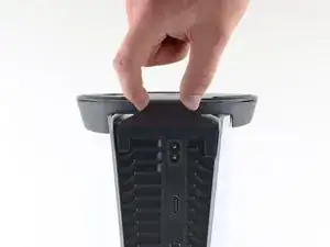
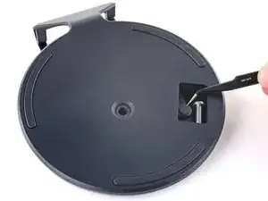
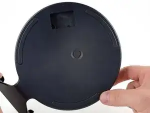
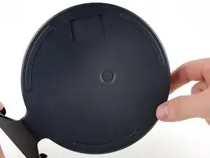
If your PlayStation 5 is in its vertical orientation, flip it upside down so the stand is facing up.
-
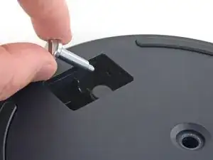
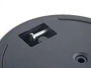
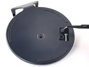
Use a coin or a flathead screwdriver to remove the 26.5 mm-long stand screw.
-
-
-
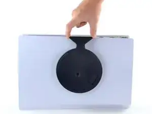
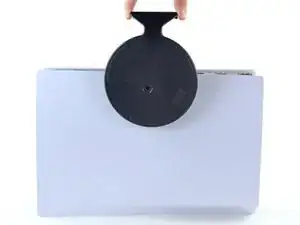
If your PlayStation 5 is in its horizontal orientation, rest it on its face with the charging port facing up.
-
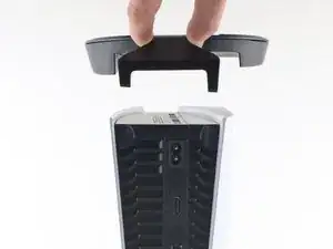
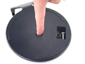
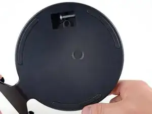
Lift the stand straight up to remove it.
-
-
-
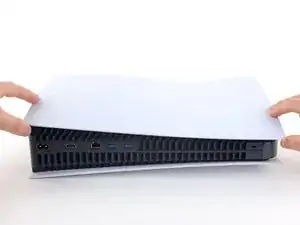
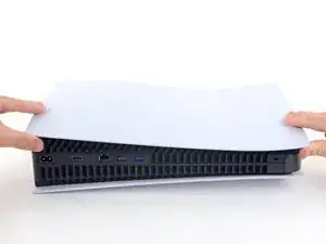
Flip the device over so that the USB and ethernet ports are on the left side from your perspective.
-
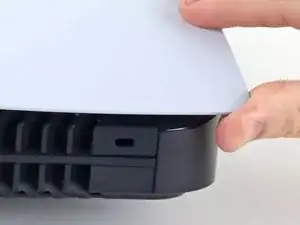
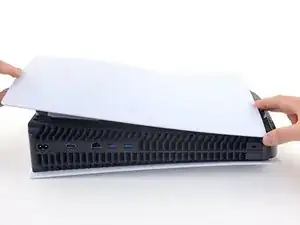
Lift up the corner of the faceplate to unclip it from the case.
-
-
-
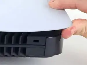
While lifting up the corner, slide the faceplate towards the bottom of the device.
-
Remove the right faceplate.
-
-
-
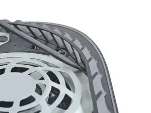
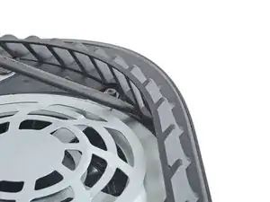
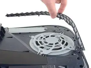
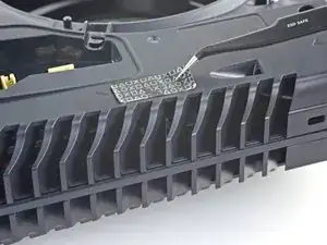
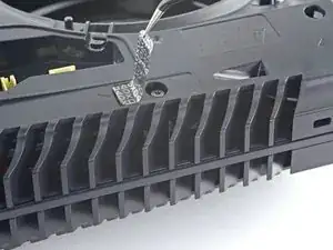
Insert the flat end of a spudger underneath the grille and into the gap above the fan.
-
Lift up with the spudger to pry the grille away from the case.
-
-
-
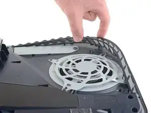
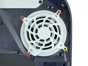
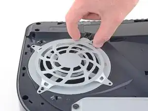
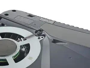
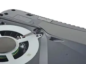
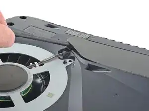
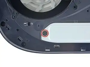
Use a TR8 Torx security driver to remove the four screws securing the fan shroud to the case:
-
Two 23.3 mm-long screws
-
One 11.4 mm-long screw
-
One 31 mm-long screw
-
-
-
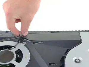
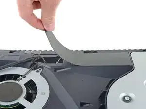
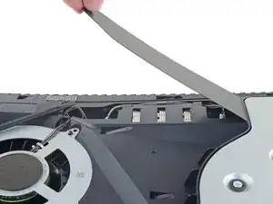
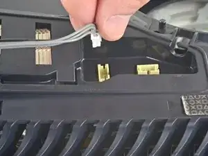
Insert the flat end of a spudger beneath the black wire cover and into the gap above the fan wires.
-
Use the spudger to peel up the wire cover until you can grip it with your fingers.
-
-
-
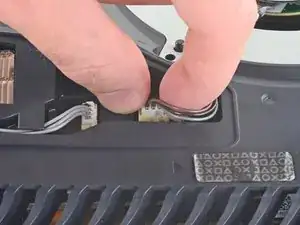
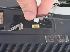
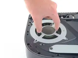
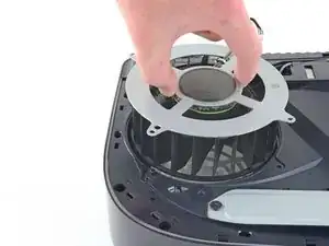
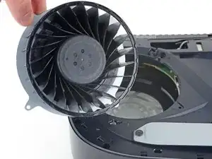
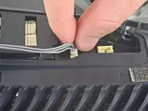
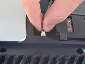
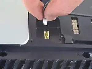
Use your fingers to grip the edges of the fan cable connector, and pull up to disconnect it from the motherboard.
-
-
-
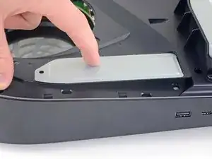
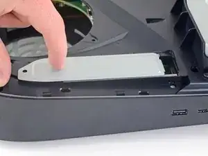
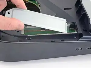
Use your finger to slide the SSD cover towards the top of the device to unclip it from the case.
-
Remove the SSD cover.
-
-
-
Use your fingers to grip the edges of the optical drive cable connector, and pull up to disconnect it from the motherboard.
-
-
-
Use your fingers to grip the edges of the optical drive cable connector, and pull up to disconnect it from the optical drive.
-
-
-
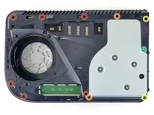
Use a T8 Torx driver to remove the eleven screws securing the case:
-
Six 18.6 mm-long screws
-
Two 23.3 mm-long screws
-
Two 43.2 mm-long screws
-
One 7.3 mm-long screw
-
-
-
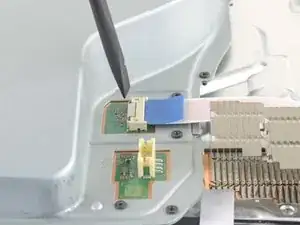
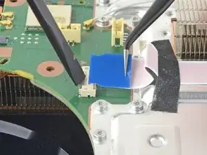
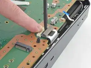
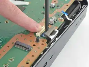
Use the flat end of a spudger to press down on the optical drive connector's metal locking tab.
-
With the metal tab depressed, use a pair of tweezers to pull the blue pull tab directly away from the connector to disconnect the cable from the optical drive.
-
-
-
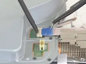
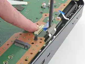
Use a pair of tweezers to pull the blue pull tab directly away from the connector to disconnect the power and eject button ribbon cable.
-
-
-
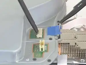
Use a pair of tweezers to pull the blue pull tab directly away from the connector to disconnect the LED ribbon cable.
-
-
-
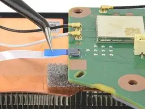
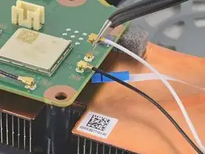
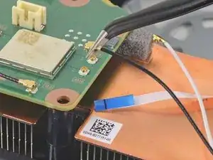
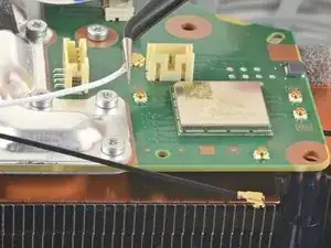
Use a pair of tweezers to grip the white Wi-Fi antenna wire at its metal base, as close to the connector as possible.
-
Lift the wire's connector straight up to disconnect it from the motherboard.
-
Repeat for the black Wi-Fi antenna wire.
-
-
-
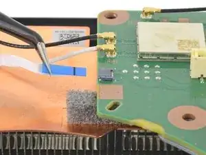
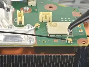
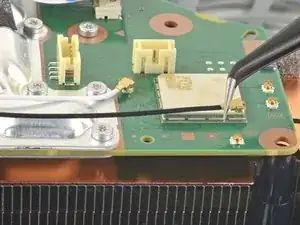
Use a pair of tweezers to grip the black or blue power supply antenna wire at its metal base, as close to the connector as possible.
-
Lift the wire's connector straight up to disconnect it from the motherboard.
-
Repeat for the white power supply antenna wire.
-
-
-
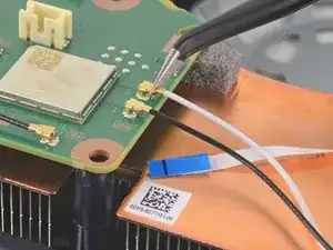
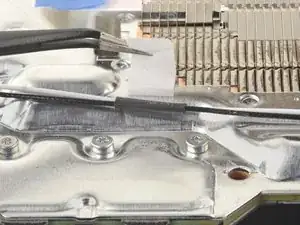
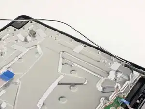
Use a pair of tweezers to peel back the white sticker holding the antenna wires to the top shield plate.
-
Remove the antenna wires from underneath the sticker.
-
Press the white sticker back down onto the top shield plate so it can be reused.
-
-
-
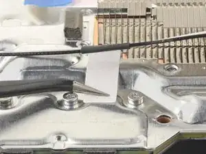
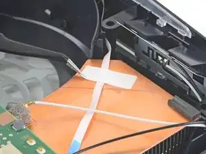
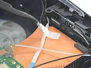
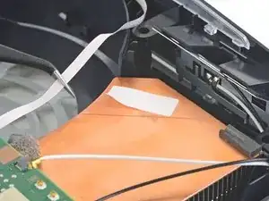
Use a pair of tweezers to peel back the white sticker holding the LED ribbon cable to the heat sink.
-
Remove the LED ribbon cable from underneath the sticker.
-
Press the white sticker back down onto the heat sink so it can be reused.
-
-
-
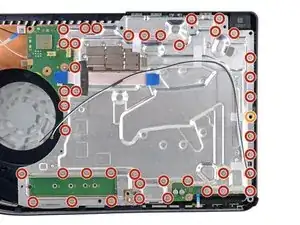
Use a T8 Torx driver to remove the forty-two screws securing the top shield plate:
-
Forty-one 7.3 mm-long screws
-
One 43.2 mm-long screw
-
-
-
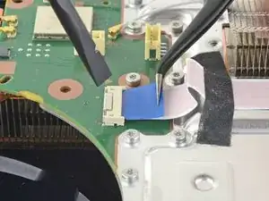
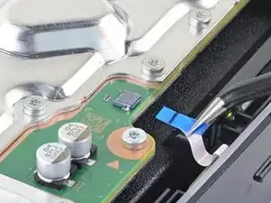
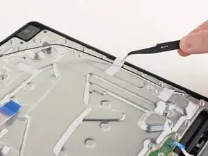
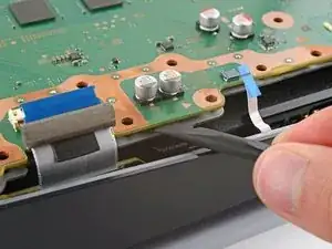
Use your finger to depress the metal locking tab on the USB board cable's board connector.
-
With the metal tab depressed, place the flat end of a spudger against the insulating foam pad on the ribbon cable and pull it directly away from the connector to disconnect it.
-
-
-
Use a Phillips screwdriver to remove the 11 mm‑long SSD screw.
-
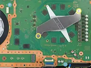
Use a Phillips screwdriver to remove the two 11.8 mm‑long APU tension bracket screws.
-
Use a TR8 Torx security screwdriver to remove the two remaining 7.3 mm‑long main board screws.
-
-
-
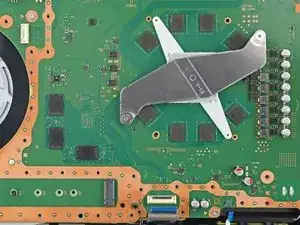
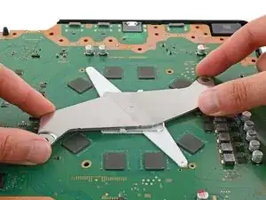
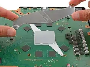
Lift and remove both APU brackets from the board.
-
Put the bracket with plastic arms on first so the pegs go into their cutouts.
-
Then, put the metal bracket onto the plastic one so they're perpendicular and the screw holes line up.
-
-
-
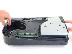
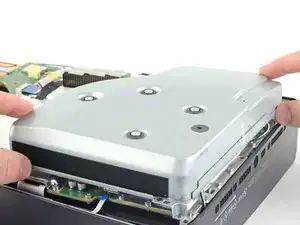
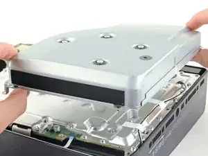
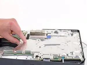
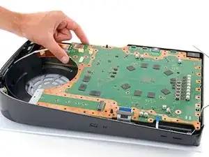
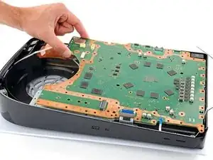
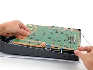
Gently lift the edge of the motherboard with the large cutout to partially separate it from the bottom shield plate.
-
With the board lifted, insert the flat end of a spudger between the board and the bottom shield plate and gently twist to separate them. Work your way around the perimeter of the board.
-
-
-
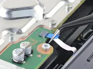
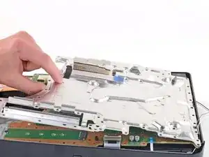
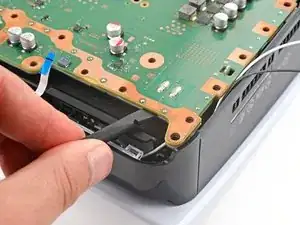
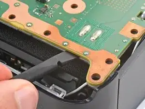
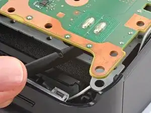
Insert the flat end of a spudger between the board and the lower shield plate, by the two parallel solder joints near the corner with the power button.
-
Twist the spudger to lift the two prongs under the board out of their socket.
-
-
-
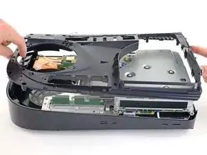
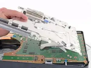
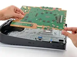
Remove the main board, flip it over, and carefully lay it on a clean work surface, so the APU is facing up.
-
Make sure all cables that connect to the board are out of the way so they don't get trapped underneath.
-
Carefully flip the board over so the APU is on the bottom, making sure no liquid metal spills.
-
Keep the board level and lower it into place.
-


To reassemble your device, follow these instructions in reverse order.