Introduction
If rotating the rear thumbwheel elicits no or inconsistent response from a powered on camera, it may need replacement. Follow this guide to learn how to remove and replace the rear thumbwheel.
-
-
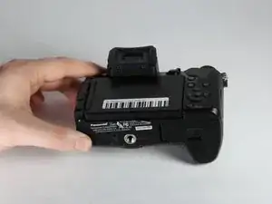
Unlock and open the battery compartment on the bottom of the camera.
-
Remove both the battery and SD card.
-
-
-
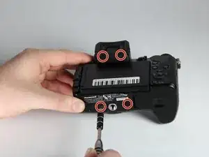
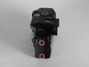
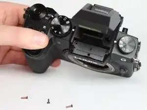
Remove the four indicated 3.0mm long black screws from the bottom of the camera and the viewfinder housing using a PH0 Phillips screwdriver.
-
-
-
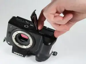
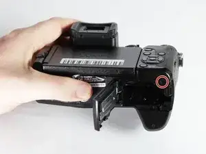
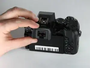
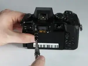
Remove the viewfinder eye cup by pulling up and out from the bottom to separate the locking clips from the camera.
-
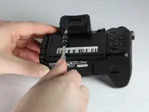
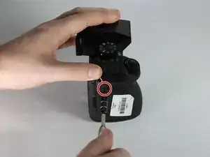
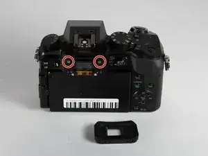
Remove the two indicated silver 3.5mm long screws adjacent to the viewfinder screen using a PH0 Phillips screwdriver.
-
-
-
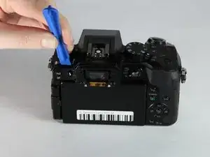
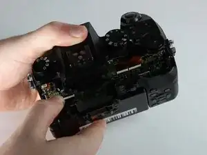
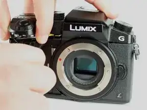
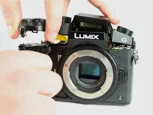
Use an iFixit opening tool (or similarly long and thin object) to insert into the gap between the two camera halves and pry the camera apart from the top.
-
-
-
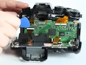
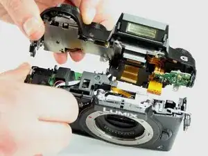
Remove the two indicated ribbon cables before separating the two halves of the camera.
-
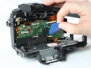
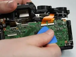
Using a flat object, pry open the black tabs above the ribbon cable connectors by gently pulling away from the motherboard.
-
-
-
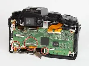
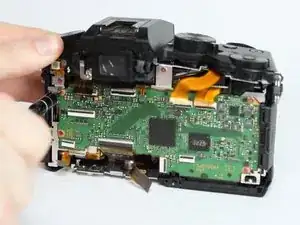
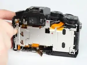
Remove the 4 indicated flex cables from top of mainboard
-
Remove the indicated small flex cable from top of mainboard.
-
-
-
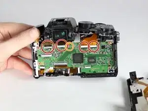
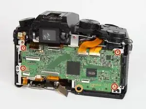
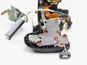
Remove the 4 indicated red 3.0mm long screws from the corners of mainboard using a Phillips PH0 screwdriver.
-
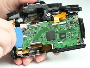
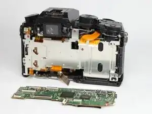
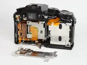
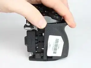
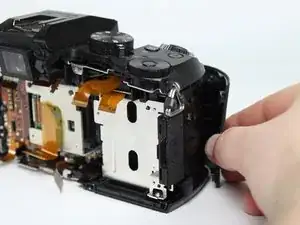
With the eyepiece facing away from you, pull up on the main PCB from the left side and then pull it away from the chassis.
-
There is a plastic locking tab on the bottom of the camera that holds the mainboard PCB.
-
-
-
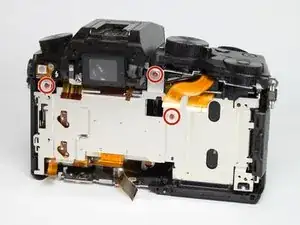
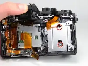
Remove the three indicated red 3.0mm screws from heat sink shield using a Phillips PH0 screwdriver, then remove the heat sink.
-
-
-
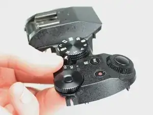
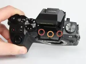
Use a Phillips PH0 screwdriver to remove the two indicated black 6.0mm long screws from top of camera, underneath the flash mechanism.
-
Remove the indicated black 4.0mm long screw from the top of the camera.
-
-
-
Remove the three indicated silver 5.0mm long screws from the back of the camera and the right side using a Phillips PH0 screwdriver.
-
-
-
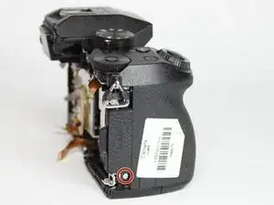
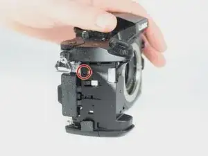
Remove the indicated black 4.0mm long screw from the side under the front cover using a Phillips PH0 screwdriver.
-
-
-
Remove the indicated silver 5.0mm long screw from under the front cover using a Phillips PH0 screwdriver.
-
-
-
Remove the five indicated black 4.0mm long screws from the top plate shield using a Phillips PH0 screwdriver.
-
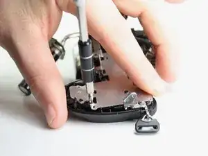
Remove the black 6.0 mm long screw from shoulder strap eyelet.
-
-
-
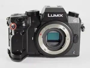
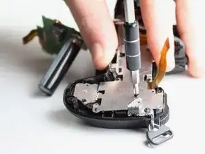
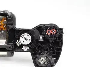
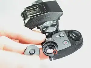
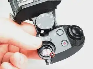
Remove the indicated black 4.0 mm long screw using a Phillips PH0 screwdriver.
-
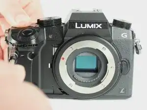
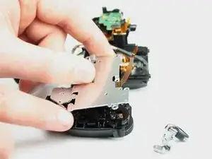
Lift away the circular plastic cover.
-
-
-
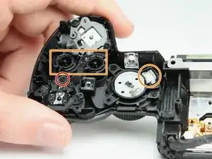
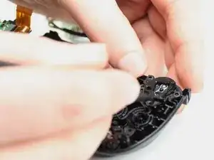
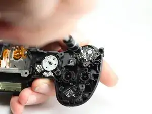
Rotate the upper cover so that the plastic section of the rear thumbwheel is upright.
-
Carefully remove the plastic upper cover.
-


To reassemble your device, follow these instructions in reverse order.