Introduction
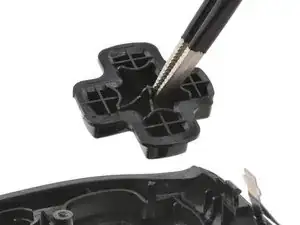
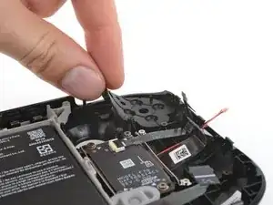
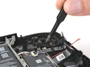
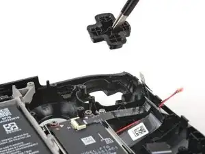
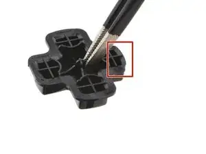
Use this guide to replace the D-pad (directional pad) and its membrane in your Steam Deck OLED.
Remember to follow general electrostatic discharge (ESD) safety procedures while repairing your device.
Tools
Parts
-
-
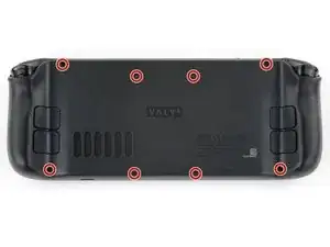
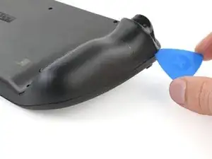
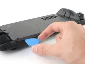
Insert an opening pick at an upward angle between the back cover and the front shell near one of the triggers.
-
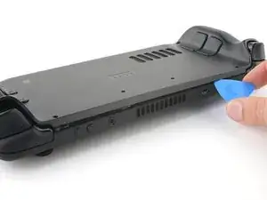
Slide your pick along the edge of the handle to release the clips securing it to the front shell.
-
-
-
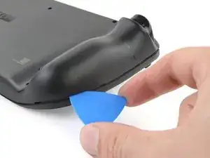
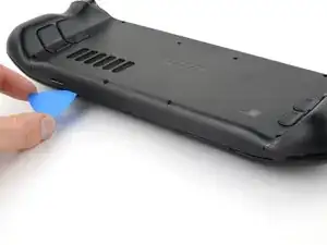
Reinsert your pick and slide it along the top and bottom edges until the back cover feels loose.
-
-
-
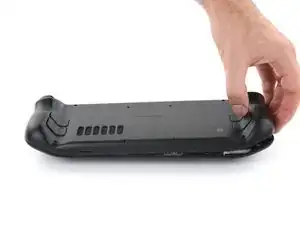
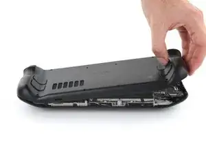
Grip the unclipped handle and pull it away from the front shell to release the remaining clips.
-
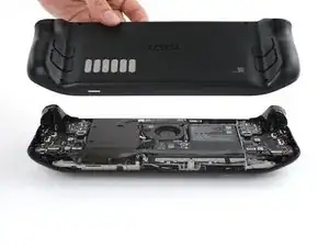
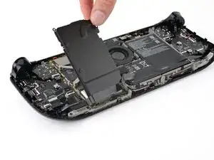
Remove the back cover.
-
-
-
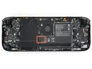
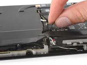
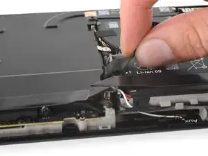
Grip the battery cable pull tab, located to the left of the battery.
-
Firmly pull the battery cable straight away from the motherboard shield (toward the battery) to disconnect it.
-
-
-
During disassembly, skip the next four steps.
-
Reinstall the two 3.8 mm‑long screws to secure the motherboard shield.
-
Reconnect the interconnect cable ZIF connector.
-
-
-
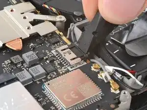
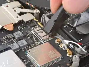
Use the flat end of a spudger to slide the battery connector into its socket on the motherboard.
-
-
-
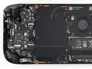
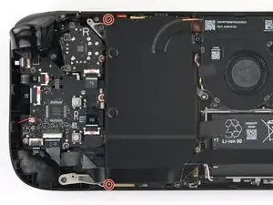
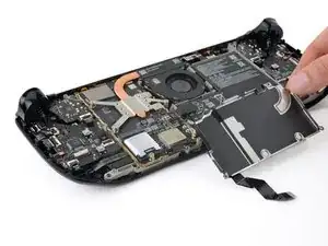
Use your T6 Torx driver to remove the two 3.8 mm‑long screws securing the motherboard shield.
-
Lift the top edge of the motherboard shield up and flip it over the bottom edge of the frame, away from the motherboard.
-
-
-
Use the point of a spudger to flip up the small locking flap on the left thumbstick ZIF connector.
-
Use tweezers or your fingers to grip the cable's pull tab and slide the connector straight out of its socket to disconnect it.
-
-
-
Flip up the small black locking flap on the left thumbstick cable ZIF connector.
-
Slide the connector straight out of its socket to disconnect it.
-
-
-
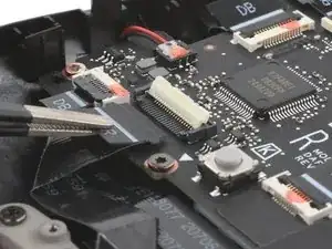
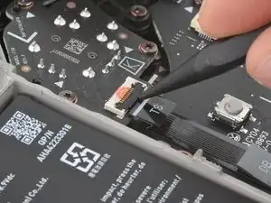
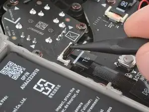
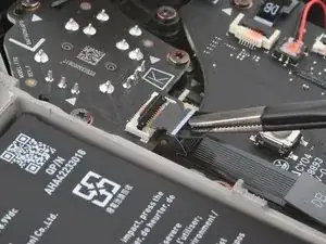
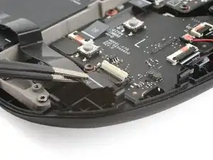
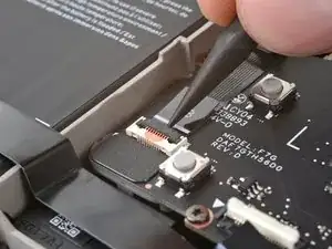
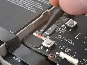
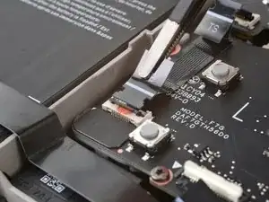
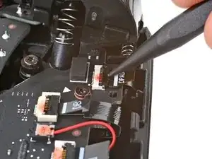
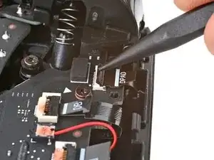
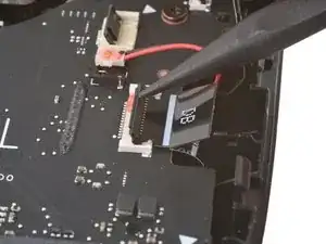
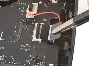
Flip up the small locking flap on the D‑pad ZIF connector, located in the top right corner.
-
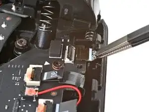
The pull tab on this connector may be labeled DPAD.
-
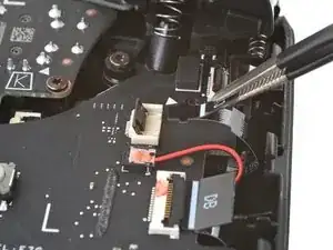
Slide the connector straight out of its socket to disconnect it.
-
-
-
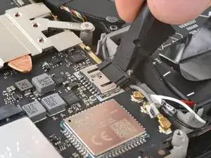
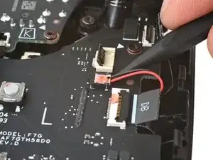
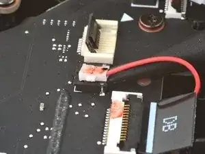
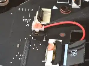
Insert the point of your spudger under the neck of the haptics cable connector.
-
Gently pry up to disconnect it.
-
-
-
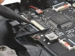
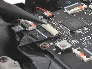
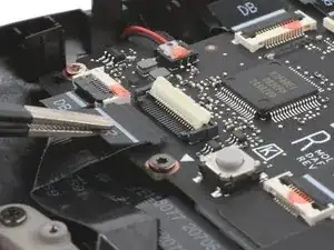
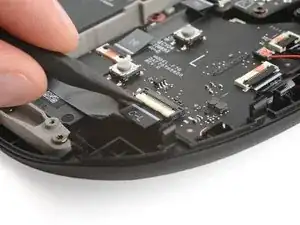
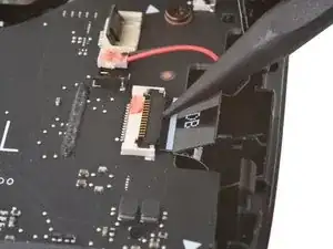
Flip up the small locking flap on the touchpad board cable ZIF connector, located just below the haptics connector.
-
Slide the connector straight out of its socket to disconnect it.
-
-
-
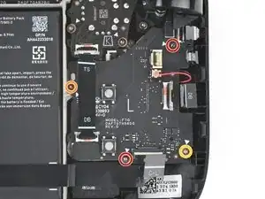
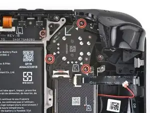
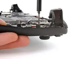
Use your T6 Torx driver to remove the four screws securing the left button board:
-
Two 5.9 mm‑long screws
-
One 3.8 mm‑long screw
-
One 4.9 mm‑long screw
-
-
-
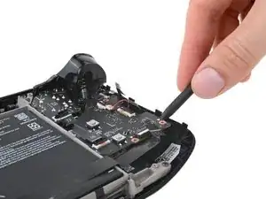
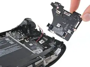
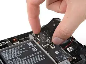
Insert the point of your spudger between the bottom right corner of the button board and the frame.
-
Pry up until you can grab the button board with your fingers.
-
Remove the button board.
-
-
-
Use your T6 Torx driver to remove the three 5.9 mm‑long screws securing the right thumbstick.
-
-
-
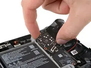
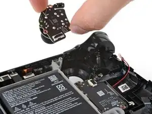
Grip the edges of the thumbstick board and rotate it counterclockwise to clear the trigger.
-
Remove the thumbstick.
-
-
-
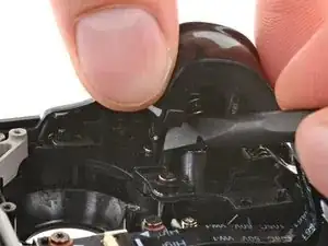
Place the flat end of a spudger onto the inside edge of the trigger's left clip.
-
Use your fingers to push the trigger toward the left as you wedge the spudger between the clip and the peg.
-
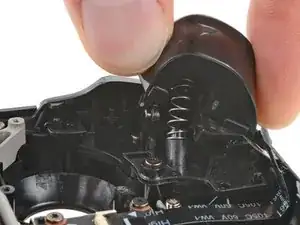
Use your spudger to pivot the trigger clip out, away, and up from the peg to unlatch it.
-
Check to make sure that the trigger spring is properly aligned. Test the trigger action before continuing reassembly.
-
-
-
Use your T6 Torx driver to remove the three 5.9 mm‑long screws securing the left bumper assembly.
-
-
-
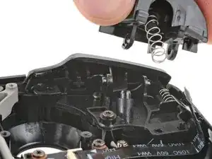
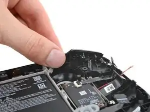
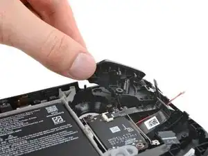
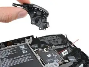
Grip the left arm of the bumper assembly and lift it off its alignment pegs.
-
Slide the assembly to the left to clear the tab on the right edge of the frame.
-
Remove the assembly.
-
To reassemble your device, follow these instructions in reverse order.
Repair didn’t go as planned? Try some basic troubleshooting, or ask our Steam Deck OLED answers community for help.
