Introduction
The micro-B USB connector on the back is flimsy and easily loses the cable.
So this guide describes how to substitute the USB connector with a USB-C type. This makes the USB stronger and the cable stays attached.
A USB4520-03-1-A SMD USB connector is chosen as the replacement part.
-
-
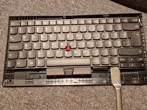
Remove the frame with a soft thin plastic tool (or finger-nails)
-
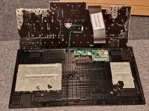
Carefully remove the keyboard from the back-cover. There is quite a lot of double sided tape. Be careful to not bend the metal frame of the keyboard.
-
As a result, you will be able to separate the keyboard from tha back cover. Only two flex PCB cables are still connecting them.
-
-
-
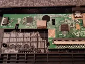
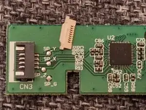
Both flex PCB connections need to be disconnected. This is done by lifting the lids on CN2 and CN3.
-
Careful to not lose the lid of connector CN2. It might come lose.
-
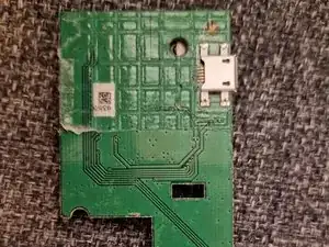
The PCB needs to be removed from the back shell. It is also glued in with double sided tape. Fortunately the back of the PCB is not having any components.
-
-
-
The USB-C connector component chosen was the USB4520-03-1-A made by GCT
-
You can buy it e.g. at Digi-Key
-
-
-
After unsoldering the Micro-B connector the sides of the rectangular cutout needs to be filed out very little to make space for the slightly wider new connector
-
File out also the opening in the back shell to allow the new part to fit through.
-
-
-
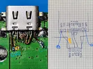
In the image the soldering and how it maps to the pads on the PCB are shown.
-
The GND can be connected to the large copper area. Just scratch away a bit of the green isolating layer. A bit of flux helps.
-
The soldering of the data lines is abit fiddly and rather for people with some soldering skills. Thin coil wire is a helpful.
-
In yellow the CC2 connection is shown. It requires a 5.1kOhm resistor to GND for correct identification by USB standard. The yellow rectangle represents the small SMD resistor.
-
If rotation of the cable is not needed, the data lines can be soldered to only the two 1DP and 1DN pins.
-
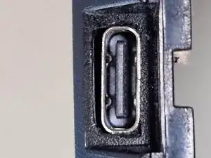
After testing, reassemble the whole keyboard. Thelast image shows how the USB-C fits into the opening.
-
Arbeite die Schritte in umgekehrter Reihenfolge ab, um dein Gerät wieder zusammenzubauen.
One comment
It's worth noting that, as long as it's not too badly damaged, the original micro-b connector can be repaired and solidified by pushing down on it and putting a drop of solder on top of it. I followed this guide and found that I didn't need to go as far as replacing the connector to make the keyboard usable again.