Introduction
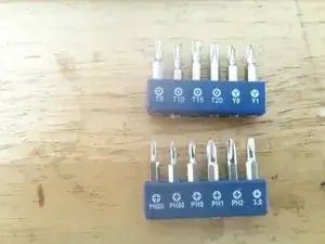
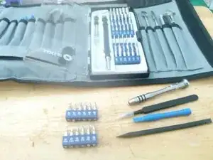
Tools
-
-
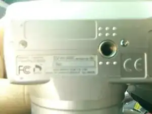
remove the 2 Phillips 00 screws from the bottom
-
remove the 1 Phillips 00 screws from the side
-
remove the 2 "Y" screws from the other side
-
-
-
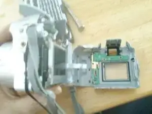
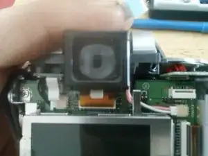
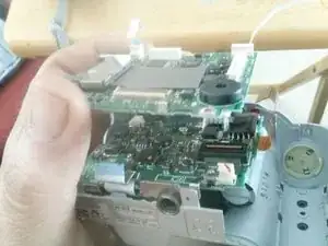
you should have already disconnected the copper ribbon cable and the molex connector with the pink and white wires.
-
wiggle the view finder gently until it comes lose
-
-
-
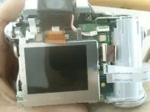
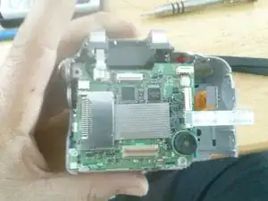
there is a small white ribbon cable attached to the battery compartment and the cameras logic board verify that it's disconnected
-
there is a molex connector with a black wire and a red wire coming from the battery compartment going to the cameras logic board. disconnect this wire from the logic board.
-
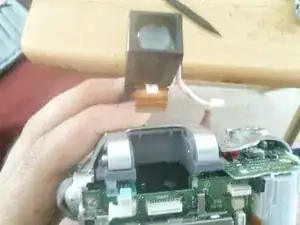
using your plastic pry tool carefully free battery compartment from the camera housing
-
-
-
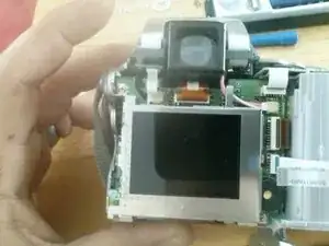
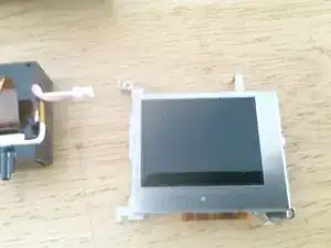
remove the 2 Phillips screws securing the LCD one is in the upper left corner and the other is on the lower right corner
-
gently lift the top of the LCD panel towards you
-
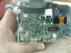
use a plastic pry tool to release the latch that secure the cable to the logic board
-
gently pull the ribbon cable from the logic board
-