Introduction
Tools
-
-
Remove the 8 mm M3 Phillips head self tapping machine screws.
-
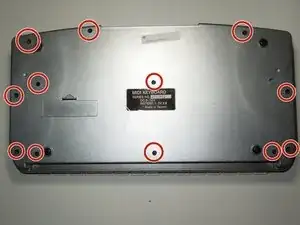
Remove all 13 of the back plate screws.
-
-
-
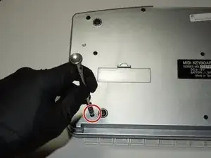
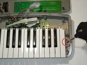
Remove the two highlighted 10 mm M3 galvanized machine screws using the J1 head fro the iFixit Tool Kit or a comparable tool.
-
-
-
Removal of Ribbon Cables
-
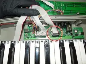
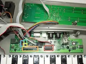
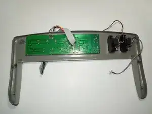
To separate the back plate, remove all five cables that connect to the motherboard but do not originate from the back plate; the key assembly, LCD circuit, rotor tuning circuit, and the pitch and modulator circuits. None of these cables require tools to remove, simply apply firm upward pressure to remove them.
-
-
-
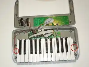
Remove the key assembly from the key board.
-
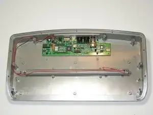
What remains is the back plate and the top plate assemblies.
-
-
-
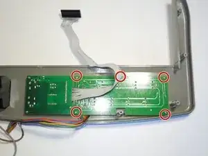
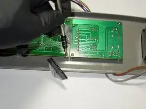
This is the location of the tuning potentiometer circuit retaining screws, 5 each 10mm long M3 galvanized Philips head machine screws
-
-
-
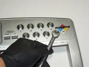
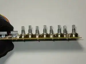
Once all eight knobs are pulled off, use the open end of a 10mm wrench to loosen and remove the potentiometer retaining nuts on all eight knobs.
-
-
-
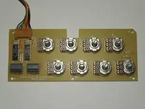
Once the retaining nuts and screws are removed, the circuit board with the attached potentiometers will easily separate from the front plate.
-
To replace the damaged potentiometer, de-solder the three connections, replace with a new potentiometer, and re-solder the connections.
-

To reassemble your device, follow these instructions in reverse order.