Introduction
This is a teardown showing how a Pwnagotchi works.For this guide, I am doing a teardown of my Pwnagotchi build
Every Pwnagotchi is different in some way, except most will have an E-Ink display such as a Waveshare and the Raspberry Pi Zero. Some Pwnagotchi units can run on different Raspberry Pi units or computers that work like the Raspberry pi!
Parts
-
-
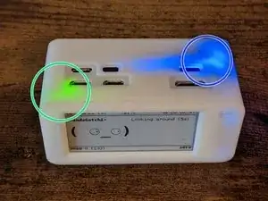
The green LED is the Rasperry Pi Zero's data indicator. This will flash as the SD card is being read/written to
-
The Blue LED is from the embedded battery in the Pwnagtochi casing. This LED only turns on when the battery is being used
-
-
-
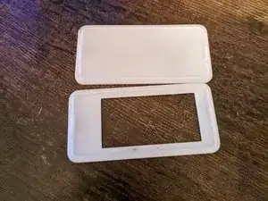
If possible, remove the outer casing of your Pwnagotchi. For this guide, our case has a removeable top and bottom so we can access the screen and battery
-
-
-
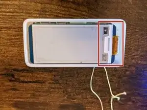
With the Top cover removed, we can see that the Pwnagotchi has a Waveshare E-Ink Display.
-
This area is covered by the 3D printed case to protect the display ribbon and electronics
-
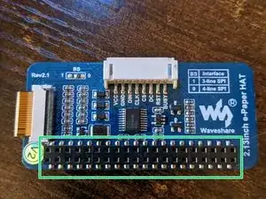
The GIPO Ports all go inside the raspberry Pi Zero, you will not need the white, 8-pin header (It can be removed if you want to have a slimmer pwnagotchi)
-
-
-
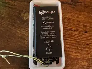
Removing the bottom case, there is a 3.7 Volt Lithium-Ion Battery powering the device with 1200mAh
-
-
-
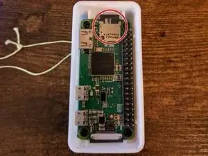
Upon removing the E-Ink Display, there is a Raspberry Pi Zero WH that runs the Operating System for the Pwnagotchi
-
The SD card runs the OS behind the Scenes, and for this case, is protected from accidently slipping out or being removed
-
-
-
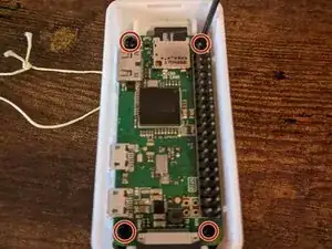
To access the battery, we will be removing (4) of the M3 screws holding the Pi down with a Phillips head screwdriver
-
-
-
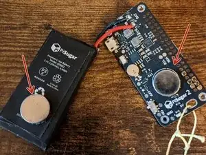
Once the screws are removed, separate the Pi and the PiSugar Battery
-
These Pins connect to the Pi and provide power for the Device
-
-
-
The battery is connected to the board via magnet and can be separated from the board to get a better look at the workings
-
-
-
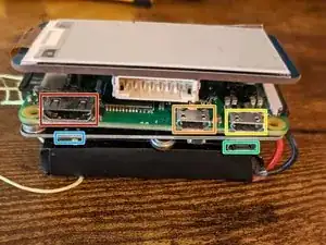
There are different connectors for this build, to better understand them, this is what they are used for:
-
Connectors/Ports on the raspberry pi zero
-
Mini HDMI Port
-
-
Power Port (Rated around 5-5.25V)
-
Ports/Connectors on the battery
-
Battery Power port
-
Battery Power Switch
-


To reassemble your device, follow these instructions in reverse order.